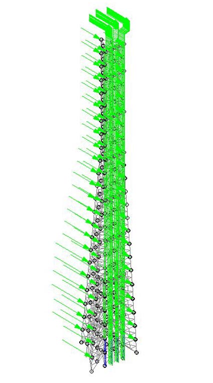
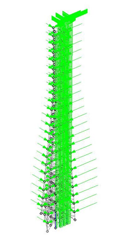
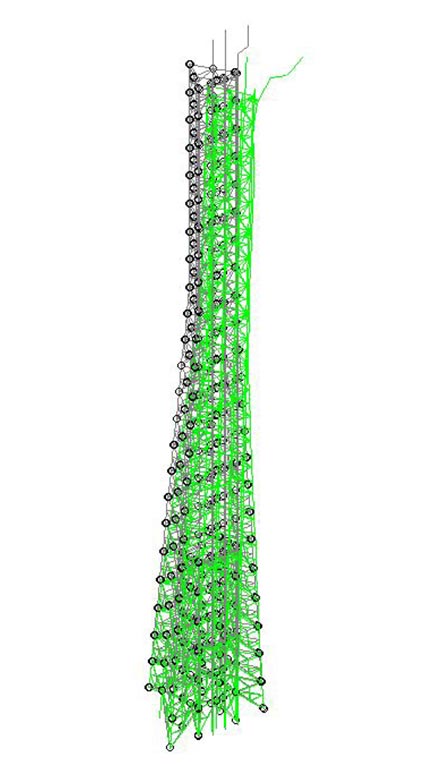
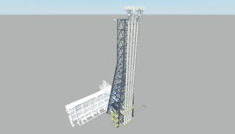
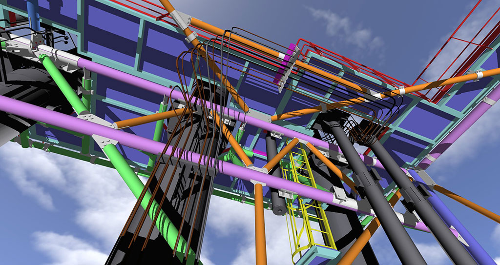
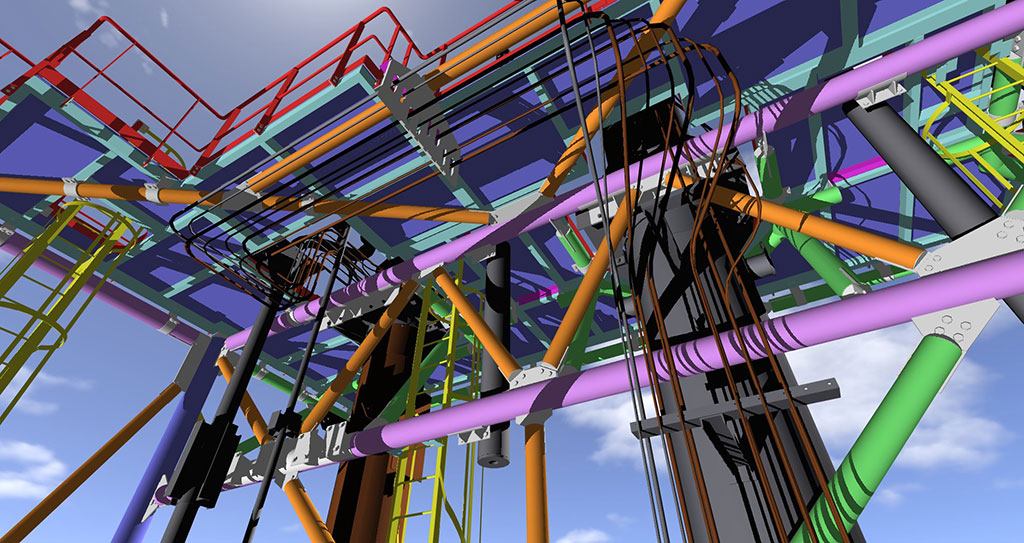
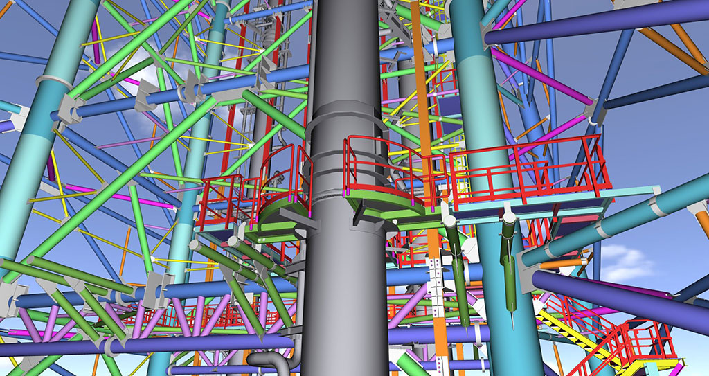
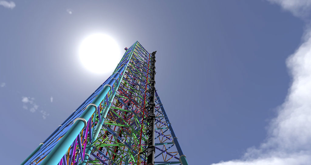
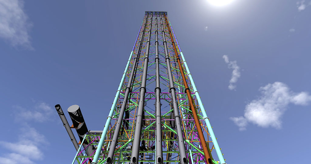
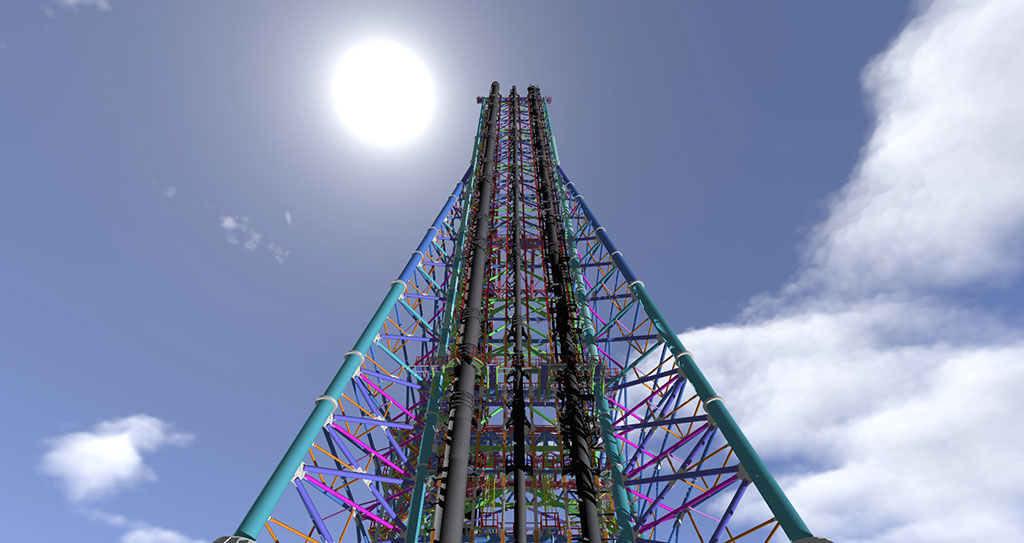
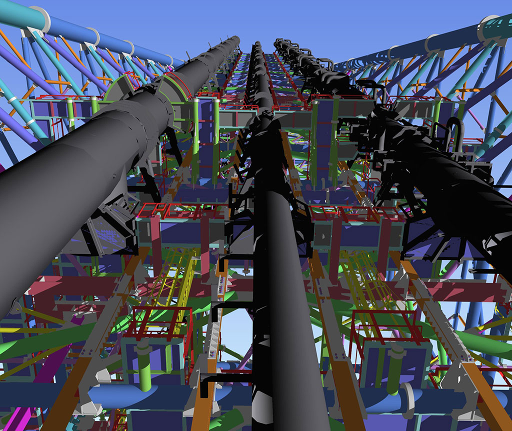
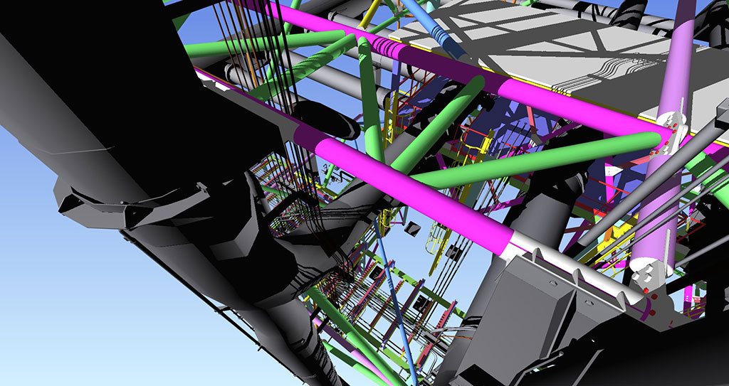
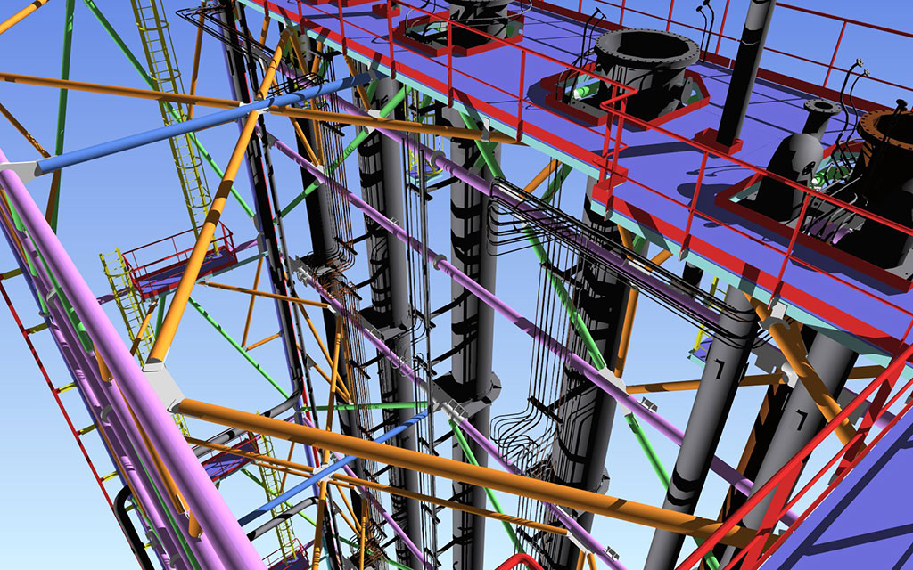
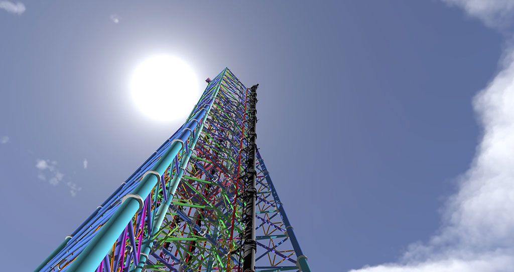
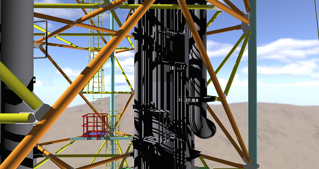
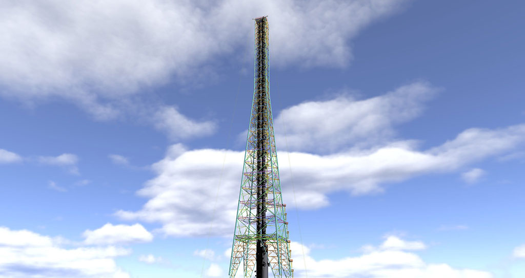
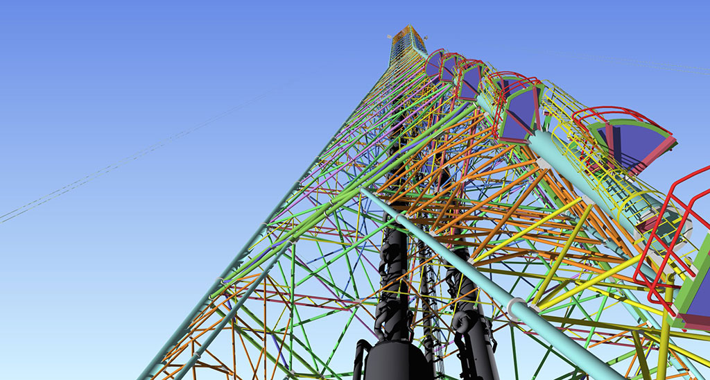
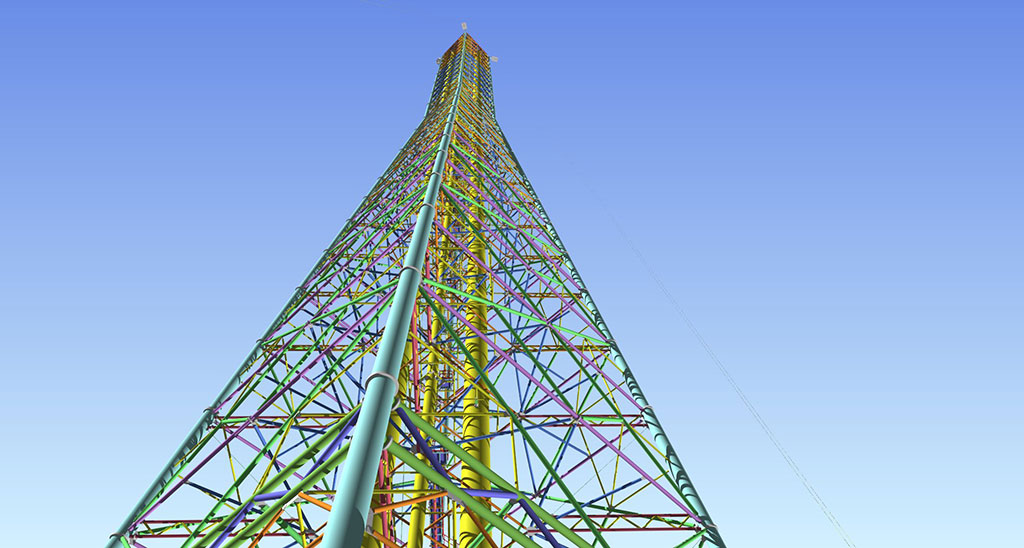
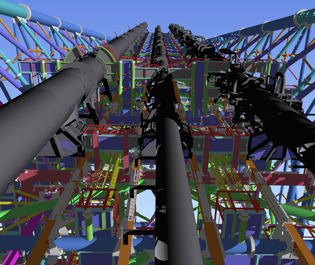
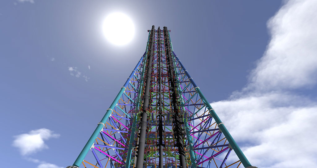
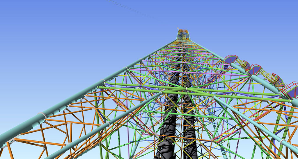
Over many years, B&C has developed a broad knowledge in the engineering of refinery, petrochemical, gas plant and offshore flares, indeed we have designed some of the tallest flare structures in the world for many of our clients often accommodating some of the most hostile climatic conditions. Our design solutions take account of the client’s preferences and the process conditions encountered.
Typically flares may be:
- Self supported flares
- Guyed flares
- Guyed derrick flares
- Derrick fixed flares
- Derrick demountable flares
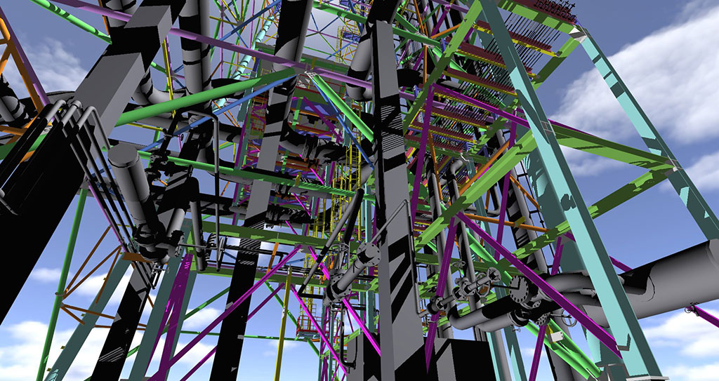
B&C designs its structures for static and dynamic loads, with attention at the effects caused by wind and seismic conditions. The use of automatic 3D design programmes allows us to prepare construction drawings in the format required by the engineer and eliminate the possibility of costly errors at the fabrication and erection phases.
We specialise in structural and mechanical calculation, lines stress analysis and in finite element analysis.
B&C offers to their Clients considerable assistance in the bid phase: we are able to determine the structure self weight with a margin of ±5%. This allows our Clients to prepare a more competitive offer and gives them a real possibility to win the order.
Our pre-design activities are much appreciated for the levels of detail. Our designs are conceived to optimise the design in terms of self weight, simplicity of fabrication, reduction of erection costs by using modularization of both the structure and process parts, safety in erection.
B&C can supply, if requested, detailed erection plans with all erection sequences and crane configurations taking into consideration the clients, and our own Health & Safety considerations.
Moreover B&C is able to supervise and undertake the complete erection process to completion.
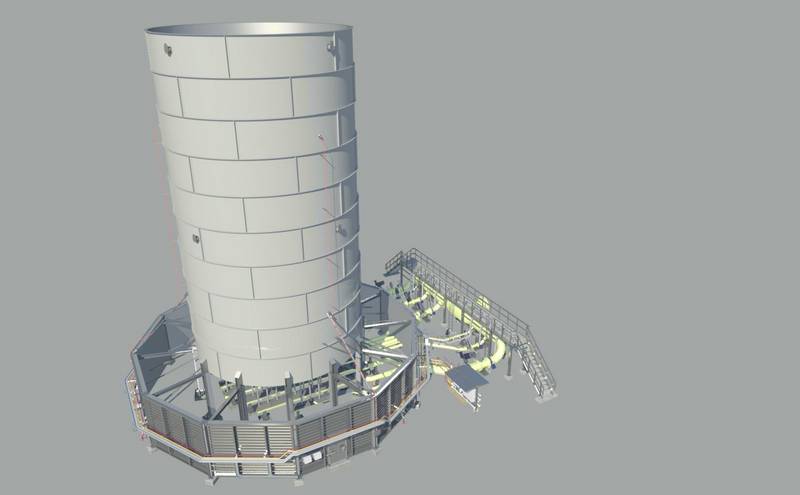
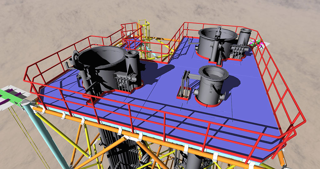
The self-supported solution can be used for flares up to 50-60 metres high and with risers with a larger diameter, since in this case the riser is also the resistant structure which can support not only the self-weight, but also the loads coming from wind or seismic action. The self-supported flares are generally equipped with ladders and with a 360° top platform in order to facilitate access to the flare tip and pilots and intermediate rest platforms.
The guyed flare solution is suitable for stack heights up to 150-160m and in this solution both the riser and the guy ropes are the resistant structures. The guy ropes are on multi levels and they are located at 120° apart on a common radius. The guyed solution is suitable for maximum design flare temperatures not higher than 200°C.
The guyed riser solution is the least expensive option but requires the largest plot area to accommodate the rope anchors and deadmen. It is usual for rope angles to be set at between 40 and 60 degrees.
For very low operating temperatures there has to be considered a loss of tension in guy ropes due to riser contraction; this may result in large deflections.
Conversely high temperature can cause a large increase in tension in the ropes due to the thermal expansion in the riser. These high temperatures in the riser can result in large compression loads from the connected ropes systems; these loads can cause riser instability and buckling.
Since riser buckling resistance is a function of the riser radius, thickness and design temperature, the higher these functions are, the lower the material resistance.
Guyed flares can be designed with either single riser, as is the norm, or exceptionally with multi risers. In this case one riser will act as the resistant structure to which the guy ropes are attached and leaving the other riser free to expand along guides as the gas temperature dictates.
The guyed flare has caged ladders and 360° top platform for flare tip maintenance operations. Further platforms can be positioned near to the guy anchor plate on the riser to facilitate the positioning and maintenance of the guy ropes.
Erection of guyed stacks entails the use of tall cranes the cost of which needs to be considered at the planning stage
The derrick guyed solution is a hybrid solution between the derrick and the guyed one. In this case a derrick of small dimensions, usually with a constant section, can support one or more risers with different temperatures even if they are highly different from one another. The derrick and the system of guy wires must support wind and earthquake loads while the risers can expand along the guides, due to the operating temperatures. This solution also requires a big area at ground level to anchor the guy wires.
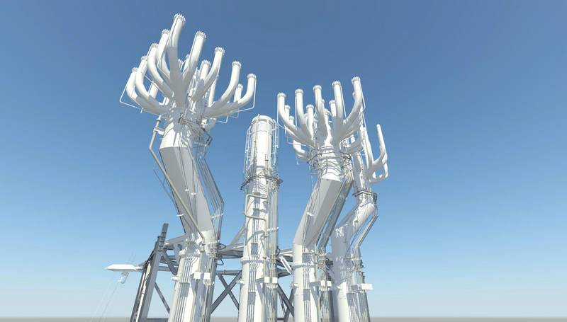
The derrick with fixed risers solution is usually adopted where there is more than one flare riser and the other solutions (self supported, guyed or guyed derrick) are not possible due to process conditions or for lack of plot space on the ground.
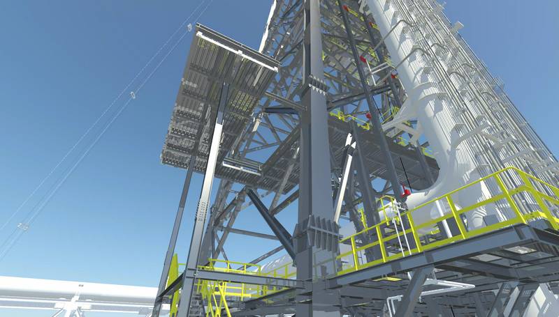
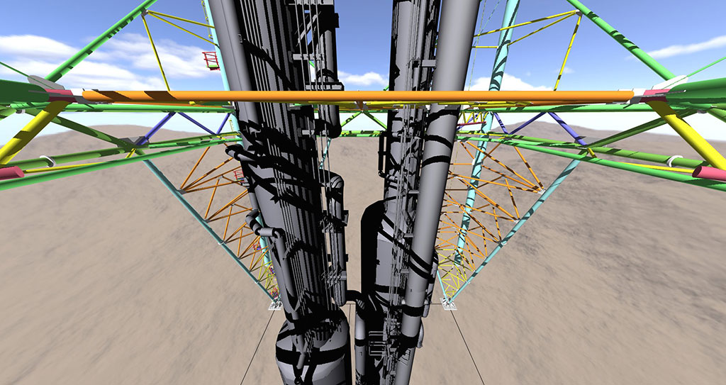
The derrick solution has no practical height limitations and allows the risers to move independent of the structure in relation to working temperatures. It may have a triangular, square, rectangular or butterfly section and can be a truncated pyramid or a flat face. This solution results in a lower self weight of the riser and permits easier erection of the risers which, maybe external to the structure and whose sections can be jointed on the ground through flanges or by welding and then overturned, thus reducing the assembling time at site.
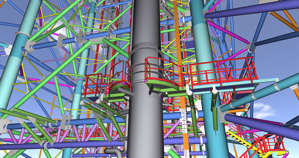
The derricks are equipped with ladders and top platform in order to facilitate access to the flare tip and pilots. Intermediate platforms can be provided both for the ACWL system and for easy access to the risers section connections.
The replacement of flare tip and pilots can be carried out with a crane or using a davit placed on the top of the derrick.
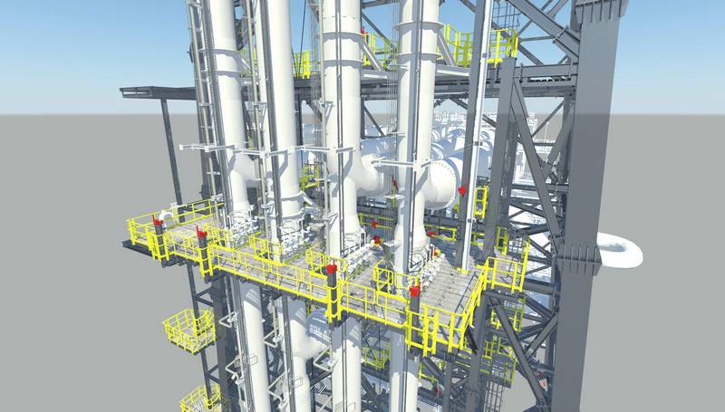
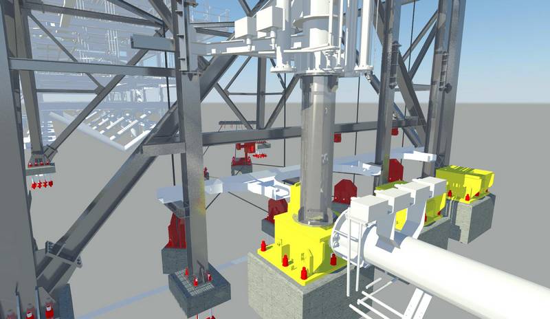
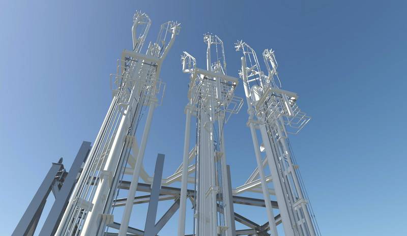
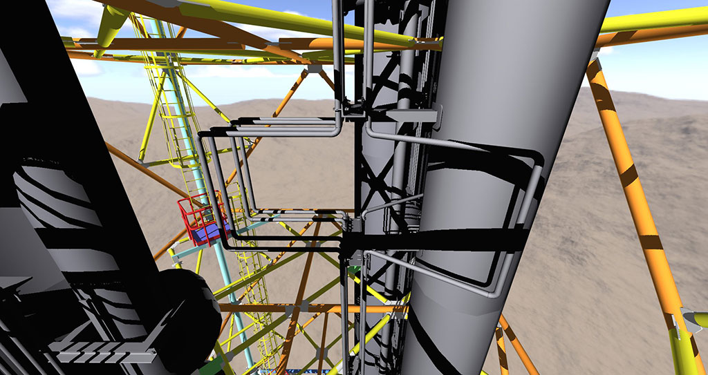
The derrick with demountable risers solution is the most complex from a construction and erection standpoint, but it allows the mounting/demounting operations for maintenance and flare tip replacement to individual risers without interruption to the service of adjacent risers and hence minimisation of plant downtime. All service, electrical or steam lines located on each riser will be lowered simultaneously.
In order to provide the optimum design derrick structures will have one of various geometric configurations: triangular, square, rectangular, butterfly or with a double derrick and after taking into consideration the number of risers, plot dimensions, height and self-weight.
The riser lifting/lowering system comprises:
- Two or three hydraulic winches (one for canting and one for lifting or one for canting and two for lifting) depending on the adopted lifting system. The winches are fitted with automatic brakes to prevent accidental release of the load and where winches are used in tandem they are automatically synchronised.
Usually the single lifting lug solution is adopted for a flat face derrick with external risers and is considered when the process design allows the risers to be near the derrick face and where the riser weight permits. The double lifting lug solution can be considered on flat faced derricks where the riser weight is excessive and where the risers are located inside the derrick. - sheaves positioned at ground and on the derrick structure
- one or two hoisting blocks
- an overturning beam on derrick
- lifting beams on the derrick
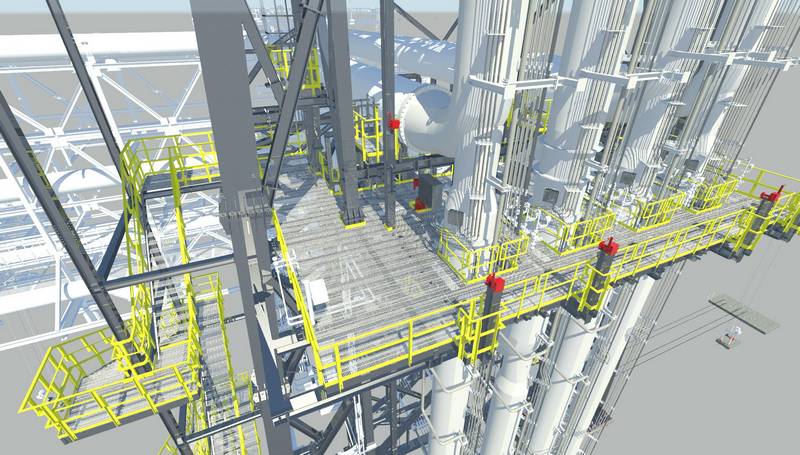
- overturning platforms that permit bolting/unbolting operations on risers, service and steam lines and electrical cable connection/disconnection during the erection/maintenance activities.
- risers with support arms with sprung rollers and guide rails for each riser
Even though the initial investment for the demountable solution is greater it provides considerable advantages:
- it allows the maintenance operations on single riser, service and steam lines, electrical cables without the disruption of all the processes connected to the flare
- It allows the maximum prefabrication of 20-24m length risers sections, which can be shipped to jobsite completely dressed with steam, pilot gas and service lines resulting in a reduction site operations and consequently erection costs and time
- Especially in the case of higher derricks it results in significant financial savings in large crane mobilisation and utilization during maintenance operations.
- Multiple risers permit a smaller plot space
- Extra space on a derrick may allow for additional risers for future expansion.
Usually demountable derricks are designed complete with stairs from grade to the working platform and with caged ladders from the platform to the top platform. Working platforms incorporate drawbridges to facilitate improved access to connections.
The demountable option may be complemented by a demountable Aircraft Warning light (ACWL) system that can be:
- a rope system: the lamps are fixed to a double rope from the derrick top and that can be lowered by a manual winch;
- a rail system: the lamps are fixed to a steel support that can moves on rails positioned along the derrick face; the lamps may be lowered by manual/electrical winch.

